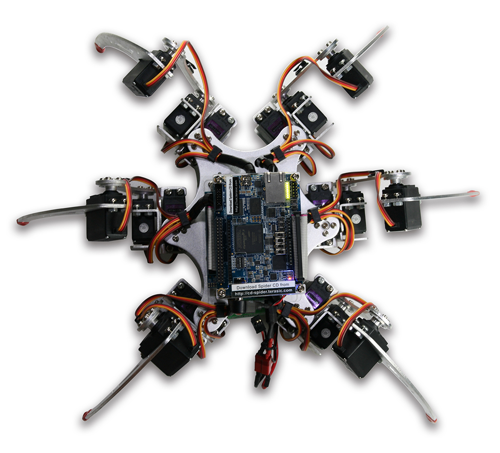
The Terasic Spider is a six-legged walking robot which is driven with 18 servo motors. These 18 servo motors are controlled by PWM signals generated from the Altera DE0-Nano-SoC board embedded inside the Terasic Spider. The Terasic Spider itself can be remotely controlled by a bluetooth enabled Android device. The software app that we developed can control the Terasic Spider to move in four directions, swing based on the g-sensor data, and even complete a dance with pre-defined movements.
All the source codes of the Terasic Spider is available with the kit. You can modify the code to improve or to change the Terasic Spider's functions according to specific applications. The source codes include Android project, Linux application project, and a Quartus project.
Note that there is a 2x20 GPIO expansion header available on the DE0-Nano-SoC board. You are free to use it to expand functions, such as camera, ultrasonic, or anything else.
Specification
Spider Specification
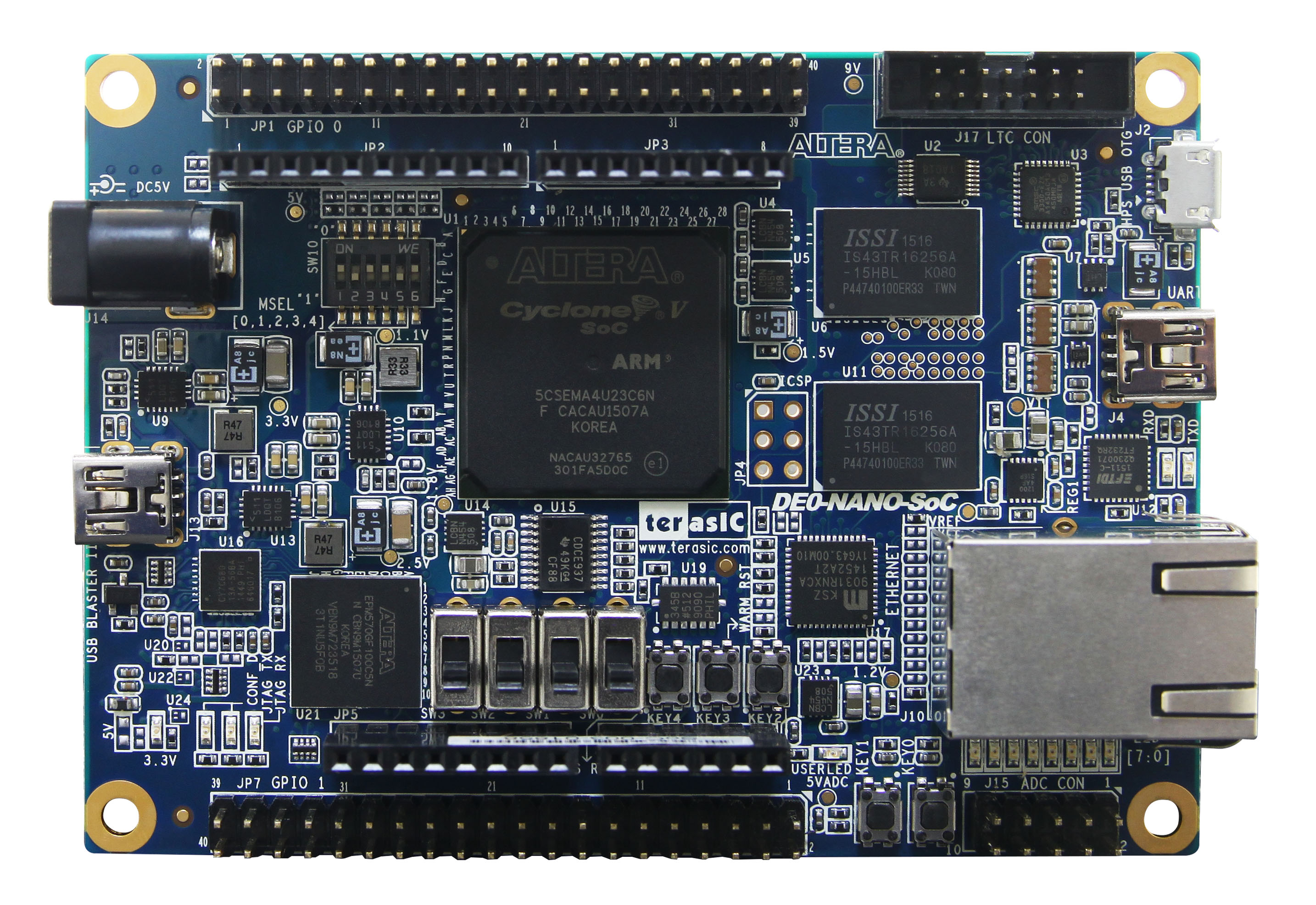
- DE0-Nano-SoC Altera SoC FPGA board for the spider control
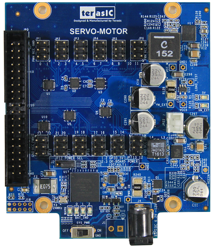
- Servo Motor Card for servo motor driving
- Metal gear servo motor - MG996R
- Aluminum body
- Remote control through bluetooth
- Power from 12V DC or Battery
- Open Source

DE0-Nano-SoC Board Features
- Altera SoC - Altera Cyclone® V SE 5CSEMA4U23C6N
- FPGA
- 40K programmable logic elements
- Serial configuration device – EPCS128
- USB-Blaster II onboard for programming; JTAG Mode
- 2 push-buttons
- 4 slide switches
- 8 green user LEDs
- Three 50MHz clock sources from the clock generator
- Two 40-pin expansion header
- One Arduino expansion header (Uno R3 compatibility), can connection with Arduino shields.
- One 10-pin Analog input expansion header. (shared with Arduino Analog input)
- A/D converter, 4-pin SPI interface with FPGA
- HPS (Hard Processor System)
- 925MHz Dual-core ARM Cortex-A9 processor
- 1GB DDR3 SDRAM (32-bit data bus)
- 1 Gigabit Ethernet PHY with RJ45 connector
- USB OTG Port, USB Micro-AB connector
- Micro SD card socket
- Accelerometer (I2C interface + interrupt)
- UART to USB, USB Mini-B connector
- Warm reset button and cold reset button
- One user button and one user LED
- LTC 2x7 expansion header

For more details, please visit "DE0-Nano-SoC": http://de0-nano-soc.terasic.com
Servo Motor Card Features:
- 2X20 3.3V GPIO Interface
- Drive 24 servo motors at most
- Fuse protection for each servo driving port
- Build-In Altera CPLD and Power Monitor Chip:
- Battery voltage monitor
- Total current monitor
- Auto shutdown when battery is low or total current is too high.
- P.S. Source code is available for users to modify according to their application.

Servo Motor Card
System Block Diagram

(Music Source: "Paint the Sky" by Hans Atom )
