ȸ»ç¼Ò°³
Çù·Â»ç
Terasic-FGPA Series
All FPGA Main Board
- Stratix III, IV, V
- Arria II. V
- Cyclone II, III, IV, V
- Bundle Solution
- USB Blaster
- max10
Daughter Card
- Interface conversion
- Video & Image
- Networking
- AD/DA
- Capsense
- Multimedia
- RF
SOC Platform
Microtronix-FPGA Series
IP Core
HSMC Daughter Card
Configurable Processor
FPGA Board
- HD Dev Solution
University Training Classes
Universities Classes using the DE2 Series
Altera ¿Â¶óÀÎ µ¥¸ð
Design Software
Embedded Processors
Licensing
Bundled Solutions
ARM Development Kit
ARM Development Kit
Single board computers
Computer-on-Module
AS ¼ö¸®
dimocore.com/terasicrepair
ÀÚ·á½Ç
°í°´¼¾ÅÍ
°øÁö»çÇ×
¹®ÀÇ°Ô½ÃÆÇ
 
 
Terasic-FGPA Series > Daughter Card > Multimedia
   
VEEK-MT2-C5SoC 
 
°¡    °Ý : °ßÀû¹®ÀÇ
Áß    ·® : 100g

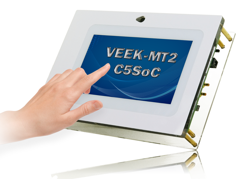
The Video and Embedded Evaluation Kit - Multi-touch, Second Edition, on Cyclone¢ç V SoC Development Board (VEEK-MT2-C5SoC) is a comprehensive embedded design environment with everything developers need to create processing-based systems. VEEK-MT2-C5SoC delivers an integrated platform that includes hardware, design tools, intellectual property (IP) and reference designs to develope embedded solutions for a wide range of applications. The fully integrated kit allows developers to rapidly customize their processor and IP to best suit their specific application. The VEEK-MT2-C5SoC features the Altera Cyclone¢ç V SoC development board with Altera Cyclone¢ç V SX SoC FPGA, and a capacitive 7¡± TFT LCD with 800x480 resolution which natively supports 5 point touch and multi-touch gestures. A 8-megapixel digital image sensor with auto focus, ambient light sensor, Gyroscope, Magnetometer, and 3-axis accelerometer makes up the rich feature-set.

The all-in-one embedded solution offered on the VEEK-MT2-C5SoC, in combination with the LCD touch panel and digital image module, provides embedded developers the ideal platform for multimedia applications with unparallel processing performance. Developers can benefit from the use of FPGA-based embedded processing system such as mitigating design risk and obsolescence, design reuse, reducing bill of material (BOM) costs by integrating powerful graphics engines within the FPGA, and lower cost.


Cyclone V SX SoC Development Board

SoC Embedded Design Suite Subscription Edition

  • ARM Development Studio 5 (DS-5¢â) Altera Edition Toolkit

  • Hardware-to-software handoff tools

  • Linux run-time software for application development

  • SoC hardware libraries for firmware development

  • Application example

Cyclone V SX SoC—5CSXFC6D6F31C6N (SoC)

  • 110K LEs, 41509 ALMs

  • 5140 M10K memory blocks

  • 224 18x18 Multiplier

  • 6 FPGA PLLs and 3 HPS PLLs

Configuration Device and USB Blaster Circuit

  • Active Serial (AS) x1 or x4 configuration (EPCQ256SI16N)

  • MAX¢ç V CPLD (5M2210ZF256I5N) in a 256-pin FBGA package as the System Controller

  • Flash fast passive parallel (FPP) configuration

  • MAX II CPLD (EPM570GM100) as part of the embedded USB-BlasterTM II for use with the Quartus¢ç II Programmer

Memory Devices

  • One 1,024-Mbyte (MB) HPS DDR3 SDRAM with error correction code (ECC) support

  • One 1,024-MB FPGA DDR3 SDRAM

  • One 256-Megabit (Mb) quad serial peripheral interface (QSPI) flash

  • One 512-Mb CFI flash

  • One 32-Kb I2C serial electrically erasable PROM (EEPROM)

  • One microSD flash memory card

Switches and Indicators

  • LEDs and displays

    • Eight user LEDs

    • One configuration load LED

    • One configuration done LED

    • One error LED

    • Three configuration select LEDs

    • Four on-board USB-Blaster II status LEDs

    • One HSMC interface LED

    • Two UART data transmit and receive LEDs

    • One power on LED

    • One two-line character LCD display

  • Push buttons

    • One CPU reset push button

    • One MAX V reset push button

    • One program select push button

    • One program configuration push button

    • Six general user push buttons

  • DIP switches

    • One MAX V CPLD System Controller control switch

    • One JTAG chain control DIP switch

    • One mode select DIP switch

    • One general user DIP switch

On-board Clocking Circuitry

  • Si570, Si571, and Si5338 programmable oscillators

  • 25-MHz, 50-MHz,100-MHz, 125-MHz, 148.50-MHz, and 156.25-MHz oscillators

  • SMA input (LVCMOS)

Communication Ports

  • One PCI Express x4 Gen1 socket

  • One universal HSMC port

  • One USB 2.0 on-the-go (OTG) port

  • One Gigabit Ethernet port

  • Dual 10/100 Ethernet ports

  • One SDI port (option for SMA connection)

  • One controller area network (CAN) port

  • One RS-232 UART (through the mini-USB port)

  • One real-time clock

Power

  • 14–20-V (laptop) DC input

Mechanical

  • 5.2" ¡¿ 8.2" rectangular form factor

Capacitive LCD Multi-touch Screen

  • 7-inch TFT LCD with pixel resolution of 800*480
  • 16 million colors (24-bit RGB)
  • LED backlight
  • 5 point Capacitive Touch

8-Megapixel Digital Image Sensor

  • 3,264H x 2,448V active pixels with Bayer color arrangement
  • Programmable frame rate up to 60FPS (1408X792)
  • Sensitivity 940mV/Lux-sec
  • Voice Coil Motor for focus control

Ambient Light Sensor

  • Precise illumination measurement under diverse lighting conditions
  • Programmable interrupts
  • 16-bit digital output with I2C fast-mode at 400 kHz
  • Programmable analog gain and Integration time
  • 50/60Hz lighting ripple rejection

MPU9250 Nine-Axis Sensors

Accelerometer Features

  • Digital-output triple-axis accelerometer
  • Programmable full scale range of ¡¾2g, ¡¾4g, ¡¾8g and ¡¾16g and integrated 16-bit
  • Self-test

Gyroscope Features

  • Digital-output X-, Y-, and Z-Axis angular rate sensors
  • User-programmable full-scale range of ¡¾250, ¡¾500, ¡¾1000, and ¡¾2000¡Æ/sec and integrated 16-bit ADCs
  • Self-test

Magnetometer

  • 3-axis silicon monolithic Hall-effect magnetic sensor with magnetic concentrator
  • Wide dynamic measurement range and high resolution with lower current consumption.
  • Output data resolution of 14 bit (0.6¥ìT/LSB) or 16 bit (15¥ìT/LSB)
  • Full scale measurement range is ¡¾4800¥ìT
  • Magnetometer normal operating current: 280¥ìA at 8Hz repetition rate
  • Self-test function with internal magnetic source to confirm magnetic sensor operation on end products


  • Size£º223*160*47 mm


Altera C5SoC User Manual Download: Here                                                              

Documents

TitleVersionSize(KB)Date AddedDownload
VEEK-MT2-C5SOC User Manual 1.0.0 29482016-09-07

Linux BSP(Board Support Package)

TitleVersionSize(KB)Date AddedDownload
Readme.txt22016-09-07
Quartus GHRD (Golden Hardware Reference Design) 2016-09-07
LXDE Desktop Image File 2016-09-07
Linux Console Image File (with Framebuffer) 2016-09-07

CD-ROM

TitleVersionSize(KB)Date AddedDownload
VEEK-MT2-C5SOC CD-ROM 1.0.0  2016-09-07
Altera C5SoC CD-ROM 14.1  2016-06-29

Please note that all the source codes are provided "as is". For further support or modification, please contact Terasic Support and your request will be transferred to Terasic Design Service.
More resources about IP and Dev. Kit are available on Altera User Forums.


VEEK-MT2-C5SoC Demonstrations

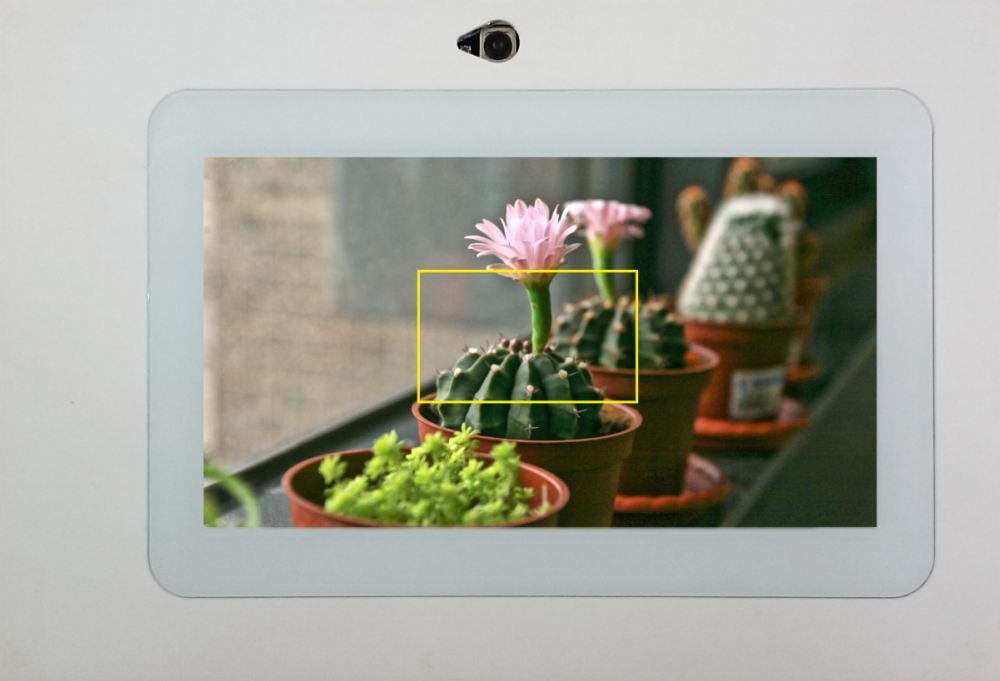
VEEK-MT2-C5SoC Camera Demonstration

This demonstration shows a digital camera reference design using the 8 megapixel CMOS sensor with auto focus and 7-inch LCD modules on the VEEK-MT2-C5SoC.
The CMOS sensor module sends the raw image data to FPGA on the C5SoC board, the FPGA on the board handles image processing part and converts the data to RGB format to ,display on the LCD module.

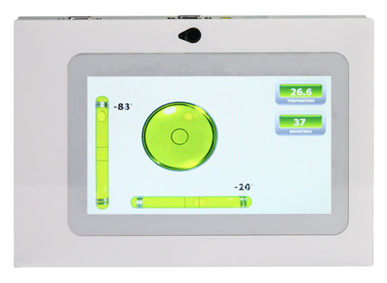
VEEK-MT2-C5SoC Sensing Demonstration

This design utilizes an embedded NIOS II cpu to communicate with the on-board digital accelerometer as well as the ambient light sensor. The accelerometer outputs as a level display, and the readings for the ambient light are displayed in the upper left-hand corner.

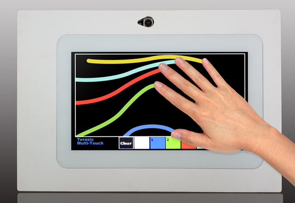
VEEK-MT2-C5SoC Painter Demonstration

This reference design showcases VEEK-MT2's sensitive capacitive touch-screen capabilities. Supporting 5 point coordinates and multi-touch gestures, this demonstration allows users to paint with five fingers. Gestures that are drawn on the canvas are displayed in the gesture indicator box left of the color palette.


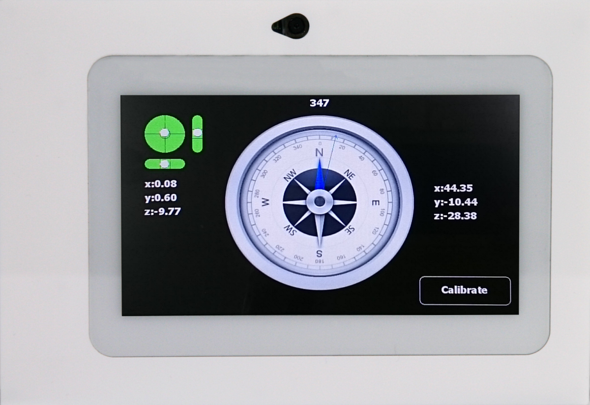
VEEK-MT2-C5SoC E-Compass Demonstration

This demonstration shows an e-compass on the LCD panel based on information measured by accelerometer and magnetometer in the MPU9250.


- Kit contents:


»óÈ£¸í
: (ÁÖ)¿ì¸²Æ¼¾Ø¾ÆÀÌ   ´ëÇ¥ÀÚ¸í : ±è¼®¹ü   »ç¾÷ÀÚµî·Ï¹øÈ£ : 211-87-88913  À̸ÞÀÏ : jun@woorimtni.co.kr
º»»ç : ¼­¿ï °­³²±¸ ºÀÀº»ç·Î 129 °ÅÆòŸ¿î 1204È£ ´ëÇ¥ÀüÈ­ : 82-2-512-7661  Æѽº : 82-2-512-7662
Copyright(C) 2011 Woorimtni Technologies All Rights Reserved.