ȸ»ç¼Ò°³
Çù·Â»ç
Terasic-FGPA Series
All FPGA Main Board
- Stratix III, IV, V
- Arria II. V
- Cyclone II, III, IV, V
- Bundle Solution
- USB Blaster
- max10
Daughter Card
- Interface conversion
- Video & Image
- Networking
- AD/DA
- Capsense
- Multimedia
- RF
SOC Platform
Microtronix-FPGA Series
IP Core
HSMC Daughter Card
Configurable Processor
FPGA Board
- HD Dev Solution
University Training Classes
Universities Classes using the DE2 Series
Altera ¿Â¶óÀÎ µ¥¸ð
Design Software
Embedded Processors
Licensing
Bundled Solutions
ARM Development Kit
ARM Development Kit
Single board computers
Computer-on-Module
AS ¼ö¸®
dimocore.com/terasicrepair
ÀÚ·á½Ç
°í°´¼¾ÅÍ
°øÁö»çÇ×
¹®ÀÇ°Ô½ÃÆÇ
 
 
Terasic-FGPA Series > All FPGA Main Board > max10
   
DE10-Lite Board 
 
°¡    °Ý : °ßÀû¹®ÀÇ
Áß    ·® : 100g

Terasic DE10-Lite is a cost-effective Altera MAX 10 based FPGA board. The board utilizes the maximum capacity MAX 10 FPGA, which has around 50K logic elements(LEs) and on-die analog-to-digital converter (ADC). It features on-board USB-Blaster, SDRAM, accelerometer, VGA output, 2x20 GPIO expansion connector, and an Arduino UNO R3 expansion connector in a compact size. The kit provides the perfect system-level prototyping solution for industrial, automotive, consumer, and many other market applications.

The DE10-Lite kit also contains lots of reference designs and software utilities for users to easily develop their applications based on these design resources.
 

Component Solution for Altera FPGAs

£ª SDRAM Memory
     Solution

£ª  Power Solution

£ª  Clock Solution


£ªAccelerometer
    Solution

£ª Capacitive Component
     Solution


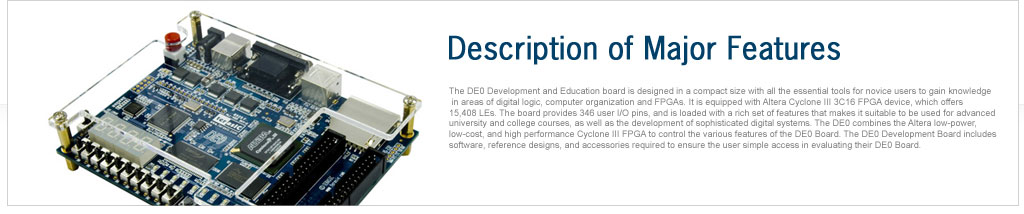
This board has many features that allow users to implement a wide range of designed circuits, from simple circuits to various multimedia projects. The following hardware is provided on the board:

FPGA Device

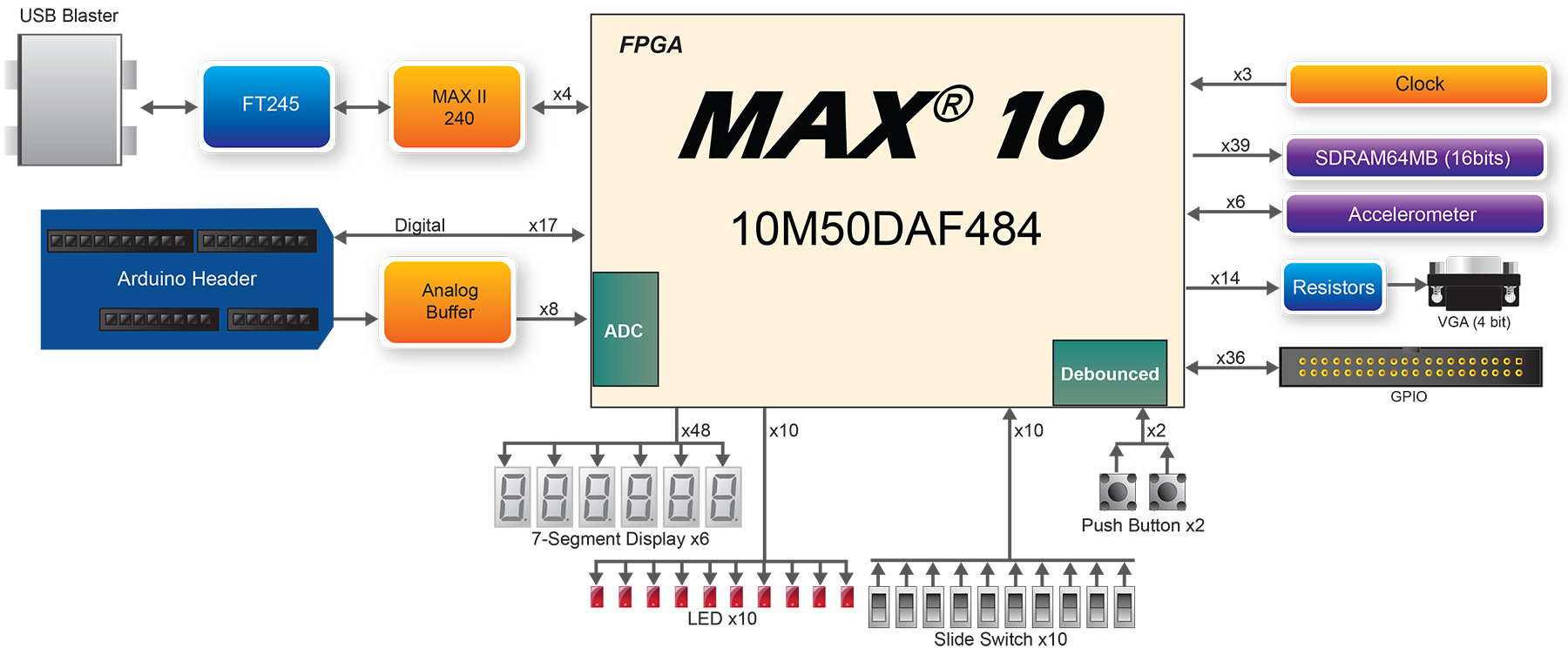
  • MAX 10 10M50DAF484C7G Device
  • Integrated dual ADCs, each ADC supports 1 dedicated analog input and 8 dual function pins
  • 50K programmable logic elements
  • 1,638 Kbit M9K Memory
  • 144 18 ¡¿ 18 Multiplier
  • 4 PLLs

Programming and Configuration

  • On-Board USB Blaster (Normal type B USB connector)

Memory Device

  • 64MB SDRAM, x16 bits data bus
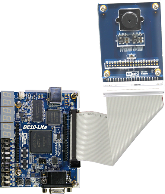
Sensor

  • Accelerometer

Expansion Connectors

  • One 2x20 GPIO Connector(voltage levels: 3.3V)
  • Arduino Uno R3 Connector, including six ADC channels.
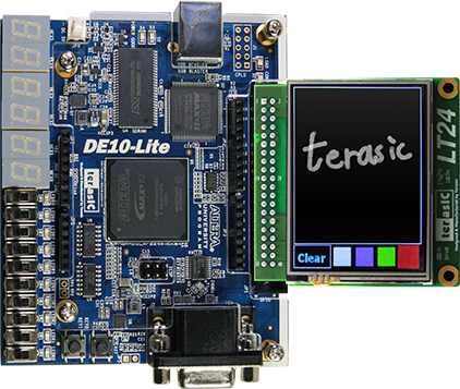
Display

  • 4-bit Resistor VGA

Switches/Buttons/LEDs/7-Segment Display

  • 10 LEDs
  • 10 Slide Switches
  • 2 Push Buttons
  • Six 7-Segments Display

Power

  • 5V DC input

Block Diagram of the DE10-Lite Board
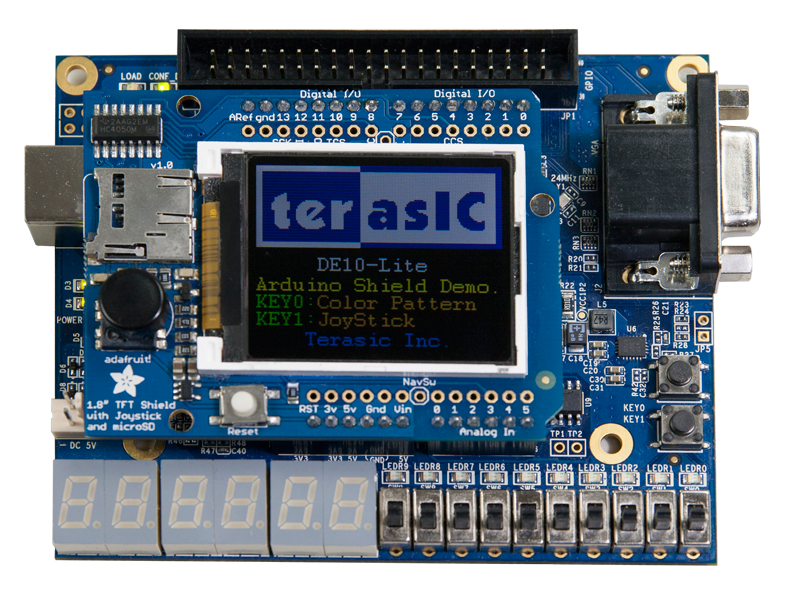
Connectivity


  • Connect with D5M

  • Connect with Arduino Shield


  • Size£º97.5*80.0 mm

Documents

TitleVersionSize(KB)Date AddedDownload
DE10-Lite User Manual 1.1 51642016-09-20

Daughter Card Demonstations

TitleVersionSize(KB)Date AddedDownload
LT24 2016-09-19
MTL2 2016-09-19
D8M-GPIO 2016-09-19

CD-ROM

TitleVersionSize(KB)Date AddedDownload
DE10-Lite CD-ROM 1.0.1  2016-09-20
Quartus Download 15.1.2  2016-06-21
ControlPanel 1.0.0  2016-06-21

3D-Printer-Case

TitleVersionSize(KB)Date AddedDownload
Top cover1062016-08-18
Bottom cover332016-08-18


»óÈ£¸í
: (ÁÖ)¿ì¸²Æ¼¾Ø¾ÆÀÌ   ´ëÇ¥ÀÚ¸í : ±è¼®¹ü   »ç¾÷ÀÚµî·Ï¹øÈ£ : 211-87-88913  À̸ÞÀÏ : jun@woorimtni.co.kr
º»»ç : ¼­¿ï °­³²±¸ ºÀÀº»ç·Î 129 °ÅÆòŸ¿î 1204È£ ´ëÇ¥ÀüÈ­ : 82-2-512-7661  Æѽº : 82-2-512-7662
Copyright(C) 2011 Woorimtni Technologies All Rights Reserved.